The EPCR6 has user-defined input/output facilities which can be used from the web UI, REST API or user scripts. The "Input/Output" main menu item leads you to the page allowing you to control the pins and ports (if they're present on your power controller model).
I/O ports
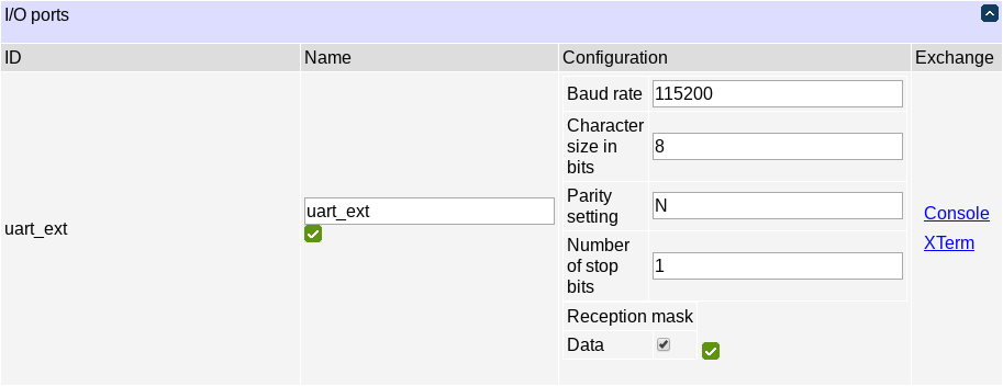
An I/O port is one or more communication channels sharing a common configuration structure. A typical example is a UART.
You can assign a descriptive name to ports. You can also choose which channels, if any, you want to receive data from. To send and receive data in the web UI, follow the "Console" (or "XTerm" if available for the I/O port type) links.

The console interface is more generic and applicable to all I/O port types. It allows you to send textual data or binary sequences encoded in hex and optionally followed by CR+LF (0D 0A). It displays received ASCII data as text and non-ASCII data as hex sequences. You can hover a received message to see the arrival timestamp.
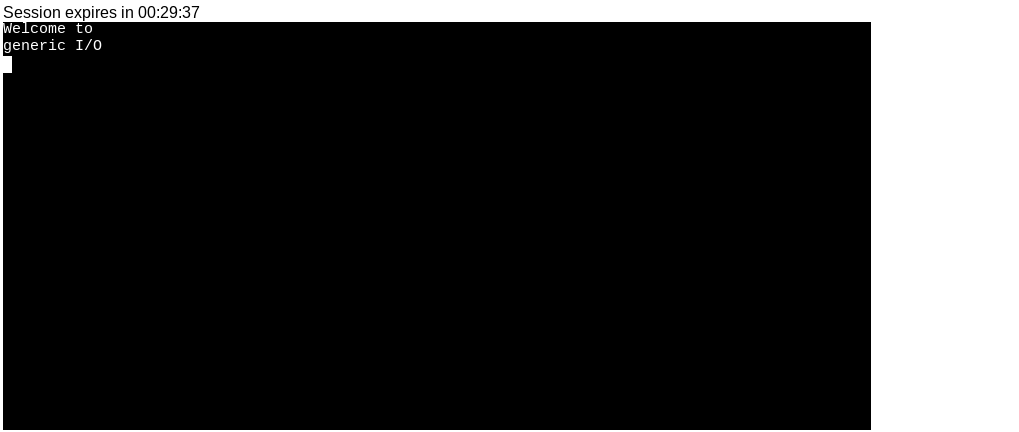
The terminal window is applicable to UART ports only. It displays an xterm-compatible terminal window and allows you to interact with it.
Ports are also available to scripting.
I/O pins and nets
The EPCR6 has pins with customizable behaviour which may be connected by nets to perform real-time operations.
I/O pin configuration
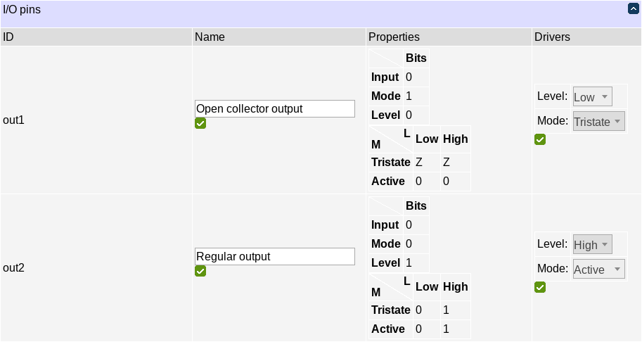
I/O pins have mode and level 'driver' parameters. Those dictate how the pin's active/tristate mode and high/low level are calculated. Some of the drivers can be locked by the hardware (e.g. open collector outputs have their level fixed at 'low', you can only switch the mode from tristate to active) so you won't be able to change them. Otherwise, they can be set to Active (High for level) or Tristate (Low for level) or to a name of a signal net (see below); then the pin's characteristic will depend on the value of the named net's value.
The input/mode/level signal bits table in pin properties indicates pin's capabilities. If input bit count is 0, the pin is output-only so it makes no sense trying to read it. If mode or level bit counts are 0, the corresponding configuration value is locked by the hardware and cannot be modified.
Usually, pins in Tristate High state are pulled up; pins in Tristate Low state aren't. Pin properties give a summary of what configurations the pin can assume, i.e. how the mode and level drivers are mapped to IEEE1164 signal states '0' (Forcing 0), '1' (Forcing 1), 'L' (Weak 0), 'H' (Weak 1) and 'Z' (High impedance).
Signal net configuration
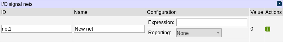
Nets are what you use when you want to have more complex pin behaviour (and also to read input pin levels as a useful side effect). A net has a value which can be assigned manually or computed using pin input values and values of nets in the previous cycle. Pins' levels and modes can be controlled by nets, with built-in transition safety (i.e. switching from pullup to active low and back will avoid the active high state). You may also receive change notifications for signal nets in user scripts.
A net's name can consist of alphanumerics, the underscore '_' and the pound sign '#' (useful for marking inverted logic).
Net names starting with the double underscore ('__') are reserved and should not be referenced or modified by users.
Net expressions are essentially characteristic equations for the nets in question.
Net values, and intermediate values appearing in a net expression, are 32-bit integers. They are interpreted by arithmetic and comparison operations to be signed in two's complement notation.
Net expression syntax is a subset of Lua syntax with the following limitations stemming from the nature of signal net definition which has to do with manipulating multibit signals:
- the whole net is described by a single expression, without any control structures;
- defining functions is not supported;
- creating tables is not supported;
- the standard library is not supported;
- 'and' and 'or' operators do not have shortcut semantics: both operands are always evaluated.
The following details concern arithmetic operators and are intended to make operation fully defined and predictable as well as compatible with Lua and expected behaviour:
- saturation arithmetic: overflow in arithmetic (but not e.g. shift) operations results in maximum/minimum representable value;
- division rounds the result down (toward negative infinity, e.g. 1/2 = 0 and -1/2 = -1);
- modulus sign matches divisor sign;
- division or modulus with zero divisor are tolerated; 0/0 = 0, otherwise division by zero results in maximum/minimum representable value; a%0 = 0.
The API is comprised of literals nil and false (corresponding to the integer value 0) and true (corresponding to the integer value 1) and the following operators and globals:
| Operator | Global | Evaluates to |
| x and y | land(x,y) | logical AND of x and y |
| x or y | lor(x,y) | logical OR of x and y |
| lxor(x,y) | logical XOR of x and y | |
| band(x,y) | bitwise AND of x and y | |
| bor(x,y) | bitwise OR of x and y | |
| bxor(x,y) | bitwise XOR of x and y | |
| shl(x,y) | x, shifted left by y bits | |
| shr(x,y) | x, shifted right by y bits | |
| x + y | add(x,y) | x + y |
| x - y | sub(x,y) | x - y |
| x * y | mul(x,y) | x * y |
| x / y | div(x,y) | x / y |
| x % y | mod(x,y) | x % y |
| x == y | eq(x,y) | 1 if x == y and 0 otherwise |
| x < y | lt(x,y) | 1 if x < y and 0 otherwise |
| x > y | gt(x,y) | 1 if x > y and 0 otherwise |
| x <= y | le(x,y) | 1 if x <= y and 0 otherwise |
| x >= y | ge(x,y) | 1 if x >= y and 0 otherwise |
| not x | lnot(x) | 1 if x==0 and 0 otherwise |
| bnot(x) | bitwise NOT of x (all bits inverted) | |
| neg(x) | 0-s complement of x (all bits inverted+1) | |
| pin[name] | the value of the named pin (name must be a string constant) | |
| net[name] | the value of the named net (name must be a string constant) | |
| apin[name] | the value of the named pin interpreted as an analog signal (see below) | |
| anet[name] | the value of the named net interpreted as an analog signal (see below) |
So, every net can reference pins (reading their input values), or nets (including itself). It is not a syntax error to reference a nonexisting net (otherwise complex schemes wouldn't be possible to enter a net at a time) or a nonexisting or unreadable pin, but such references return the value 0 (until, in the case of a net, it appears).
Standard Lua syntax rules apply to net[], etc. indexing operations, so you can address net q1 as net["q1"] or net.q1, but net #R only as net["#R].
Every net output is latched, that is, it is stored in a memory area on every step. When a net's value is read to compute another net's value, the previous step's value is used, so e.g. an expression 'not net.Q' for net Q makes sense, and produces a rapidly oscillating output. On creation, all net values are initialized with the value 0.
This latching behaviour allows for edge detection, e.g. if you have net Q you can create a helper net Q_ which copies it and introduces a one-step delay as a side effect:
Q_: net.Q
and add edge-detecting nets:
Q_rise: net.Q and not net["Q_"]

Q_fall: not net.Q and net["Q_"]
Due to this latching behaviour, situations which have a diminishing probability in real-life circuits can happen with certainty in emulated circuits. For instance, consider that you already have nets #R and #S and want to produce an SR latch on two NAND logical elements. If you naively follow the classic schematic and create the two nets:
Q: not (net["#S"] and net["#Q"])
#Q: not (net["#R"] and net["Q"])
at once, the following will happen (considering #R and #S are both 1, i.e. hold state):
- both
Qand#Qstart out with value0; - on the next step, both
Qand#Qassume the value1becausenot (1 and 0) = 1; - on the next step, both
Qand#Qassume the value0becausenot (1 and 1) = 0; - etc.
The result is not state being held, but an oscillation! If you have configured the nets in question for change reporting, the EPCR6 may become slow to respond. In a real device, the signal propagation times would never be exactly equal so the situation would be resolved into one of the stable states, but this is not so in emulation.
One possible advice on avoiding such situations is to use the minimum number of nets. E.g. a similar latch could be produced by the following net (replacing net["#Q"] in the expression for Q with the expression for #Q):
Q: not (net["#S"] and not (net["#R"] and net["Q"]))
or, equivalently,
Q: (net["#R"] and net["Q"]) or not net["#S"]
It has a single positive feedback loop and doesn't exhibit the above problem. It also explicitly makes #S dominate #R (in case of conflict, Q is 1). If you want #R to dominate, all you need is move the parentheses:
Q: net["#R"] and (net["Q"] or not net["#S"])
Analog signal handling
Analog signals (e.g. ones read from an ADC channel or an external sensor) are commonly presented in a fixed-point format as signed two's complement integers with the upper half storing the integer part, and the lower half storing the fractional part. The values of the readings match those in e.g. scripting meter.values[key].value, that is, they are the physical values measured by the channel or sensor, expressed in SI units (e.g. volts for voltage, degrees Kelvin for temperature, etc.). To handle pin or net signals in this format, reference them using apin[] or anet[] instead of pin[] and net[], respectively.
Analog signal representation matters when analog signals are operands of arithmetic or comparison operators. To ensure proper operation, it's required to use the apin[]/anet[] ('a' for 'analog') symbols to address the pins or nets you want to treat as such.
You may get a warning if you address a pin or net incorrectly (using e.g. pin instead of apin or vice versa), but otherwise this distinction is not enforced, since you may have reasons to reinterpret a value.
Additionally, analog pins represent Not-a-Number (in turn representing readings from a disconnected sensor) as all-zeros (binary value 0). It is false in a boolean context, which simplifies net coding. All other values are nonzero; zero is mapped to the binary value 1, corresponding to the epsilon value, below error margin of most sensors. The value is, however, not handled specially by any built-in functions or operators; any special handling must be implemented manually.